Friday, August 19, 2016

Yet another Tank House

After I had finished my John Krohn Tank House, which consists mainly in one single structure, I wanted to build yet another one, a little bit different.

While browsing the net for pictures of tank houses, I stumbled over the Stanley Ranch Tank House that's actually part of the Garden Grove Historical Society's Stanley Ranch Museum Historical Village.


The tank tower reminded me of a railroad watertank and I figured out that if I would find a suitable model, I would simply plank the timber bents and add a shed to it as a stand-in for a free-lanced close-to-prototype tank house.


The search for a suitable model proved to be not as easy as I'd expected. Most of the recent models were either too big or too expensive. I would only need the timber supports for my project and the rest will go to my parts box, so a cheaper model was needed. Fortunately the Model Power Water Tank did the job.


I assembled the timber bents as per the instructions, using the base of the model as a guide to align the sides until the glue had dried. But before I assembled the supports I sanded the sides smooth to eliminate the bolt heads on the cross braces. I filled in strips of .020 styrene to obtain a equalized surface to glue the siding onto.


As a base for the long shed I used a Walthers office shanty which I had lying around already assembled. I discarded the window and door castings as well as the roof. I cut pieces of novelty siding to size to fit around the tank tower. I made a cutout for a Grandt Line 5-panel door casting.
I also covered the tank platform with scribed siding to simulate planking and lined the sides with strip styrene.


I cut openings for a window and a freight door into the right siding of the shed. On the tank tower I also used the protruding timbers with the small platform. It serves as an access platform to the water tank. This tank house has no interior stairway, so I will lean a ladder against the small platform to get to the tank.


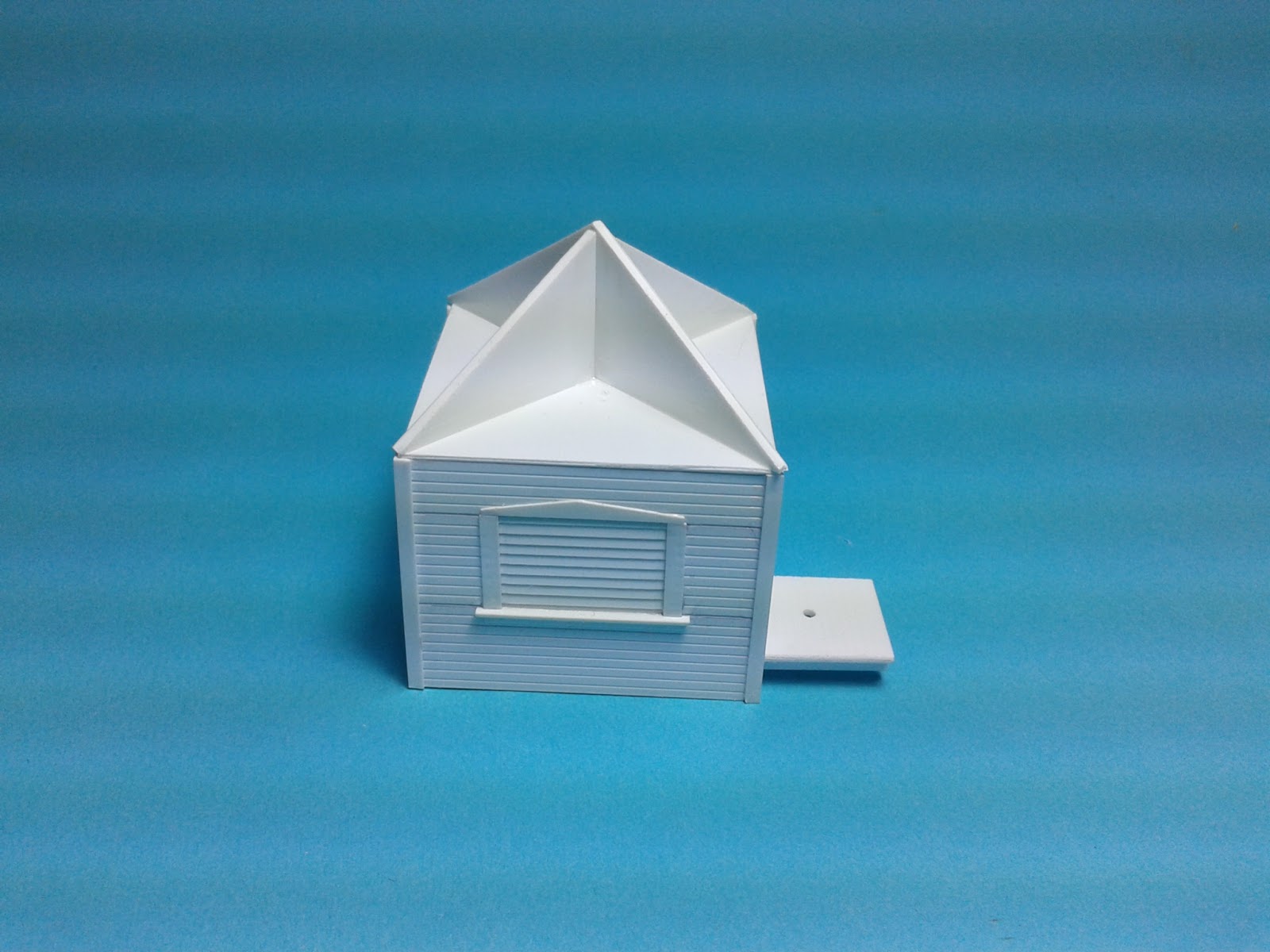
Because the tank tower walls lean inwards, I had to fit the sidewalls of the shed accordingly. This is achieved by a bit of trial and error and a few passes with a sanding stick. Then I glued the two sidewalls to each side of the Walthers shed. As shown in the picture, I used the locations of one side and the rear window as a guide for the openings of the new windows. Because the new side walls are longer than the original Walthers shed, I installed the freight door there. I also fitted the missing floor in between the original shed and the tank using a piece of .060" styrene. 


For the end wall and the window location I used the Walthers shed as a guide and glued the new wall directly to the old shed wall.


Contrary to the John Krohn Tank House, which has an enclosed water tank, this one is open. The tank on the Stanley Ranch Tank House is rather small and the one from the railroad water tank too big. I looked around for something in between. I choose a piece from a mailing tube with 2" diameter. I left the plastic plug in one side and planked the side with 1x6 and 1x4 scale lumber strips cut to size using my NWSL Chopper.
 

I applied a small bead of carpenters glue to the carton base and spread it with an old paintbrush. Then I applied the wood strips. This goes very straight forward.


I made a new roof for the shed using Plastruct Shingle sheet cut to size.


I stained the water tank with a mix of a few drops of India Ink and Isopropyl Alcohol. I applied the stain with an old paint brush. As this was my vacation project I had forgotten to take the stain mix with me. Otherwise I would have stained the wood before applying it to the mailing tube.
 

This view shows the ladder leaning to the small platform to access the water tank.
All the subassemblies and roof are only put in place and not glued yet. Now the tank house is ready for the paint shop.

Stay tuned for the finish.

Tuesday, March 22, 2016

Building a Tank House (Part 4 and finish)

 Just in time for the World Water Day, I finished my Tank House. I placed it in an appropriate surrounding for the photo, although this is not the final emplacement.


But to this step, there were still some other to do first.

Using my jig to hold the stringers, assembling the stairs was fairly easy. I attached the stairs to the second floor landing on the upper end and to a piece of plain styrene, representing a concrete footing, at the other end.


Then I glued the posts in place, taking care to keep everything straight.


I used 4x8 strip styrene for the handrails. I've cut the different pieces to size and then sanded each part until it fit snuggly between the posts. A drop of liquid cement attached them permanently.


I painted the structure white and after the paint had dried over night, I installed the staircase. As you'll see I added another sheet of styrene, to represent a concrete slab under the staircase. I tried it without, but the whole assembly would be too woobly and could only be fixed correctly when placing it on the layout.


While the glue was setting, I turned to the roof. I covered the styrene roof panels with double sided tape. This sticks very well to styrene and gives a more secure hold for the shingles.


I inteded to use the tab shingles from AMB Laser Kit, but found the package almost empty, so I decided to use the diamond shingles instead.


The shingle sheets from AMB come on self sticking backing and they are easily attached strip by strip. I approximately measured the strips I needed for each row and cut them to size. Then I peeled the backing paper off and attached the strip to the sticky roof. When finished with one side I just cut the extending strips off along the roof line with scissors.


For additional information I can only recommend the book "Tankhouse, Californias redwood water towers from a bygone era, by Thomas Cooper. I fortunately found a signed copy by the author on the internet. It shows many different types of tankhouses and what the owners made out of them since municipal water management made most of them obsolete.


Finally putting the different sub-assemblies together was a snap.


Here are the views from all the four sides. Only need some decent weathering and than it's ready for the layout.


Oh yes, I also added the shaft that powered the pump. The final place for the tankhouse is still to be determined. I shot it in an appropriate environment for now.

Well that's it for this project. Stay tuned for more to come.


Monday, March 21, 2016

RMC layout article

If you want to read how I built my home layout, Railroad Model Craftsman published my article in the October 2015 issue and it's titled Modeling AT&SF's Surf Line in Germany

If you didn't read it, dig the copy out of your magazine stash or get a back issue from White River Productions.

The article has 11 pages and a detailled track plan. The issue is worth its money because it is loaded with more great articles.


Friday, March 18, 2016

Building a Tank House (Part 3)

In this installment I will document the finishing touches of the Tank House, which proved also to be the most delicate and trickiest part of the whole building process.


On many tank houses, the stairs leading to the second floor, were inside the building. Here it's on the outside. As there are no ready-made stairs available which I could use for my tank house, I had to build them from scratch.

To do so, I first built a jig to hold and space the stair stringers correctly.


The stringers are from Campbell, cut to fit. The treads are 1x8 Evergreen strip styrene.


I only added a small drop of glue to the stringer, where the treads would go, with a needle, to avoid glueing the stringers to the jig. After the glue on the treads had dried I added more glue to fix them more securely.


Then I build a small platform and attached the stairsway to it. I drilled two holes into the platform side and inserted two bits of .019" brass wire. I also drilled two holes into the siding where the platform will be located. These pins allow for minor adjustments when building the rest of the staircase. Also I need to paint the structure and then the stairs will be in the way.


A first test fit of the stairway attached to the platform. As I mentioned before, this will be a very delicate assembly.


On this picture you may already guess the final look.


To attach the supporting posts, I fixed the assembly into the magnetic jig to hold it square and flat.


Then I turned to the windmill and added 2x4 steps. The original was wood and the model I use has a metal construction, but by adding the steps it almost looks right.
I used a 2' wide scrap piece of styrene to space the steps. Then I applied a tiny drop of cement to attach the steps.

That's it for now. Hopefully more to come during the week-end if the announced nice weather doesn't keep me out of the basement. 

Wednesday, March 16, 2016

Building a Tank House (Part 2)

Well, I started this project last summer already and due to other "obligations", it rested for some time.
When I finally got back to it, I wasn't happy with what I had already accomplished on the tank house. The supporting structure wasn't trapezoidal enough, compared to the pictures and there were also other flaws in the construction of the roof etc. So finally I decided to start all over again.


 On the picture above you see the "old" tank house, and in front of it, the new one.


The basic construction techniques stayed the same, so I don't cover these again except for some additional details I've added. You'll easily recognize the difference between both models. Above you see a first test-fit with the windmill.


During my research and the study of the six pictures from the Library of Congress site, I've found out that there are actually two more windows, one to the east and one on the north side. Using the same tried and true method, I also incorporated these windows into my new construction.


While I was at it, I also fitted a floor in. I built the enclosed tank to be removable and thought about adding an interior to the second floor. These parts of the tankhouse were often used as storage room, or housing for crop workers.


The tank top with the triangular parts for the roof supports, before assembly.


The ventilation slats are represented with rectangular pieces of clapboard siding, framed with strip styrene. Note the peaked trim and the sill. These are details I did not do on the first model.


The finished roof supporting assembly is covered with .020" scribed styrene siding with the plain side up, simulating the boards when viewed from below.


 I've cut bits of 2x4 strip styrene to represent the rafters. The roof has a two foot overhang on each side, so the rafters are visible and need to be there.


The finished rafters. Note the roof cut-out for the windmill.


With the roof completed, I test-fitted the sub-assemblies to check the overall appearance. You probably noted that the windmill is a different one. Meanwhile I decided to use the finer detailled Van Dyke windmill from Walthers.
I shortened the legs and only used the upper part of the frame.


Please drop by, to see the finishing touches.

Monday, March 14, 2016

Building a Tank House (Part 1)

 I don't know how you do it, but I have so many projects, sometimes running in parallel to each other, that keep me busy and give me some time to think things over. So here I am back again with another iconic structure for my Surf Line layout.

In fact a Tank House is nothing different than a railroad water tank, except that it is almost a unique structure only found in the western parts of the United States, like California and less in Texas and Oregon.

The Tank Houses resemble an enclosed water tank, what they basically are. The supporting legs are covered with siding and the tank itself sits on a platform and is sometimes also enclosed.

There are so many different styles and I did not find a single picture which would suggest that there ever existed a standard design.

While searching the web for pictures or plans, I found this interesting looking structure with a windmill attached to it.

On the site of The Library of Congress I found b/w pictures as well as drawings for the John Krohn Tank House. It is located in the Santa Clara County in California and compiled by the HABS under the survey number CA-2111 (Historical American Building Survey).

The description tells us the following:


"This structure is typical of the hundreds perhaps thousands of tank houses that once dotted the Santa Clara Valley landscape. They provided a means by which ground water from private wells was stored and later delivered under pressure for domestic consumption and/or agricultural irrigation. This one was built for John Krohn, who moved to San Martin from Chicago in or about the year 1912. Its redwood storage tank has been removed, but a windmill remains in place. A portion of the enclosed tower may have housed a laundry room at one time" (Source Library of Congres)

Now with all the necessary information on hand I was able to start this project without guessing.


Using my scale ruler I traced the dimensions of the four trapezoidal sides of the supporting structure (or first and second floors) on a sheet of Evergreen .060" plain styrene and cut them out.
Then I scribed the location of the doors and windows on the wall sections with an Xacto hobby knife.


 With the same hobby knife I drilled a hole in the center of the window location. This goes fairly easy, but you could also use a drill bit. The hole needs to be large enough to stick the jaw of the Micro Mark Nibbler through.


This handy tools "bites" the unwanted pieces of styrene away. I worked along the score lines until the opening was cut out. Usually there is only minor sanding necessary to make the door and window castings fit properly.


 The plain styrene only serves as a core for my structure walls. I laminate the exterior siding and sometimes also the interior sidings, if I plan an interior, to this core.


In the case of this structure I used Evergreen V-groove siding. With a liberal amount of liquid cement, I glued the plain wall sections to the back of the siding. Before cutting out the wall sections the glue needs to dry thoroughly.

On two opposite wall sections I cut the sidings flush to the core and on the other two leave the siding longer, at least the thickness of the core plus the siding. These "ears" give the structure additional strength without glueing corner braces. This is especially critical when adding an interior.
From the back side I drill small holes in the four corners. These keep the hobby knife from slipping and damaging the siding. Here I used a .010" siding. This is easy to cut from the back.


The four wall sections are now ready for assembly.


I think the Campbell windmill would give a good stand-in for the tank house.

Thanks for following my blog and stay tuned for the next installment.